This page provides a quick introduction of the steps required to generate the inputs for the Etabs panel design module.
NOTE: The app currently only supports AS3600-2018 and walls with 2 layer of reo.
This is a work in progress document. Contact us if you have any question regarding the usage/calculations.
Model the structure and run the analysis as usual.
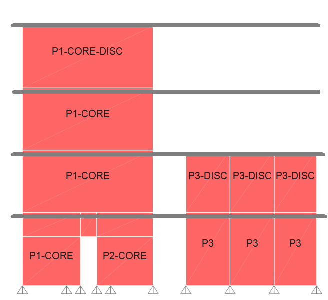
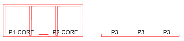
There is a specific naming convention which needs to be followed when assigning pier tags to panels:
- Limited ductile walls which experience the tension across the entire length (Walls with return walls on both sides. i.e. core walls) have a higher min. detailing reo requirement. Pier tag assigned to these panels would need to have an arbitrary postfix which can be defined in the app (Default is set to “CORE”).
NOTE: Shear walls which do not undergo full length tension would still need additional reo at both ends as per code requirement. Additional bars can be called up typical in the schedule (i.e. “ADDITIONAL 2-N16 EACH FACE EACH END”) - To check the dowel requirement at top of the panels which terminate at slab soffit, pier tags can be appended with an arbitrary postfix (Default is set to “DISC”). This check is typically required for the panels which terminate at the lower levels and tend to have considerable shear force (i.e. at podiums).
NOTE: When designing the dowels at top of the panel, the assumption is that slab thickness is adequate to provide full anchorage of the bars in shear. If this is not the case, dowel spacing needs to be manually adjusted.
Before running the shear wall design navigate to:
Design → Shear Wall Design → Assign Pier Sections… → Uniform Reinforcing…
and ensure that for each pier to be designed:
- “Material” is correct.
- “Clear Cover for Rebar” is correct.
- “Reinforcement to be Designed” is selected.
Now run the shear wall design and extract the Excel outputs required by the app.
Reactions
To extract pier reactions, select “Table: Pier Forces” from below:
Display → Show Tables… (Ctrl+T) → ANALYSIS RESULTS → Element Output → Wall Output
In “Select Load Patterns…”, “Select Load Cases…” and “Select Combos…” dialogues, ensure that only relevant cases/combinations are selected:
- G: Case/combination of dead loads (i.e. G or DL+SDL)
- Q: Case/combination of live loads(i.e. Q or LL)
- Eu: Envelop combination of the earthquake only cases
- V*/M1*: Envelop combination of the ULS combinations
- M2*: Bending moment from gravity only combination (1.2G+1.5Q).
Display the table and save as Excel file.
Forces
To extract dowel design forces, select “Table: Pier Forces” from below:
Display → Show Tables… (Ctrl+T) → ANALYSIS RESULTS → Element Output → Wall Output
In “Select Load Patterns…” and “Select Load Cases…” dialogues, deselect all load patterns and load cases. In “Select Combos…” dialogue, only select ULS load combinations which are applicable for panel design (DO NOT SELECT ANY ENVELOPS).
Ensure earthquake combinations are reported for each load step by activating:
Modify/Show Options… → Load Combination Results → Multiple Values, If Possible
Display the table and save as Excel file.
Designs
To extract panel designs, select “Table: Shear Wall Pier Design Summary – AS 3600-2018” from below:
Display → Show Tables… (Ctrl+T) → DESIGN DATA → Shear Wall Design Output → Shear Wall Summary Data
Display the table and save as Excel file.
Running the app
Use the 3 exported file from Etabs as inputs of the app. For any input field there is a help dialogue which can be accessed by holding the mouse pointer over the input.
Below are the sample input files and corresponding output file.